I've spent a fair amount of time around networking. I've worked for a small ISP, helped to set up campus and office networks and even done a fair amount of work with BGP and assisting with ISP failover and route work. However in my current role I've been doing a lot of mobile network diagnostics and troubleshooting which made me realize I actually don't know anything about how mobile networks operate. So I figured it was a good idea for me to learn more and write up what I find.
It's interesting that without a doubt cellular internet is either going to become or has become the default Internet for most humans alive, but almost no developers I know have any idea how it works (including myself until recently). As I hope that I demonstrate below, it is untold amounts of amazing work that has been applied to this problem over decades that has really produced incredible results. As it turns out the network engineers working with cellular were doing nuclear physics while I was hot-gluing stuff together.
I am not an expert. I will update this as I get better information, but use this as a reference for stuff to look up, not a bible. It is my hope, over many revisions, to turn this into a easier to read PDF that folks can download. However I want to get it out in front of people to help find mistakes.
TL/DR: There is a shocking, eye-watering amount of complexity when it comes to cellular data as compared to a home or datacenter network connection. I could spend the next six months of my life reading about this and feel like I barely scratched the surface. However I'm hoping that I have provided some basic-level information about how this magic all works.
Corrections/Requests: https://c.im/@matdevdug. I know I didn't get it all right, I promise I won't be offended.
Basics
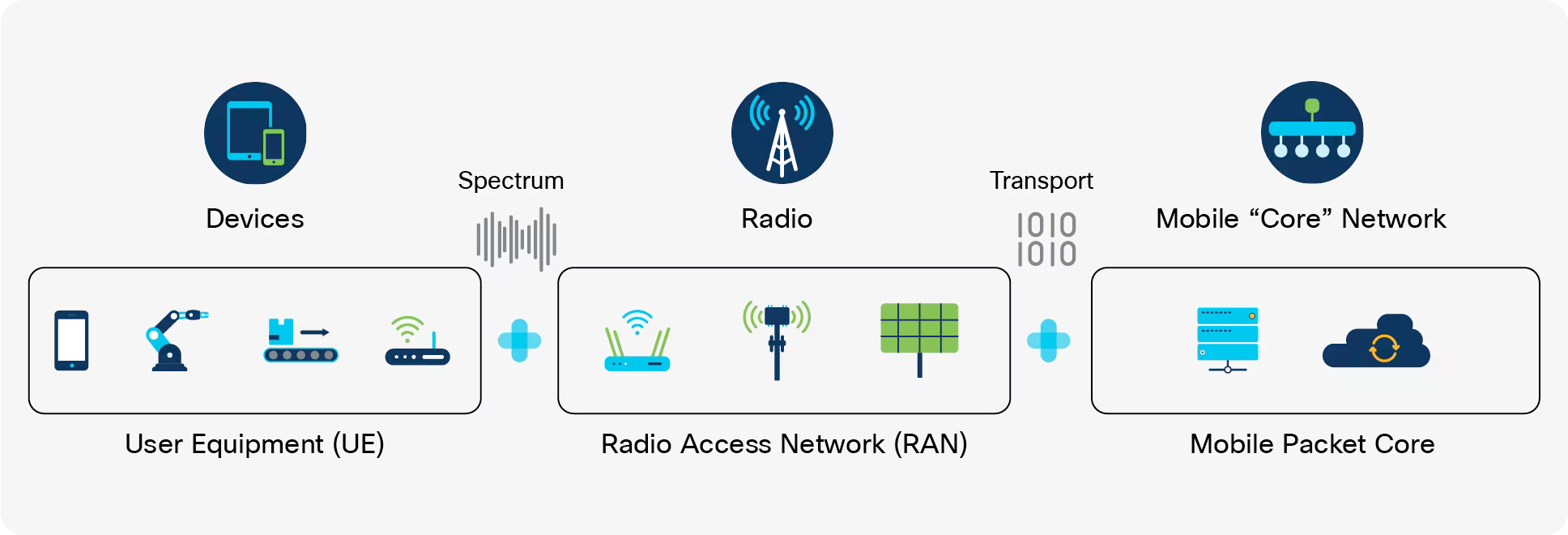
A modern cellular network at the core is comprised of three basic elements:
- the RAN (radio access network)
- CN (core network)
- Services network
RAN
The RAN contains the base stations that allow for the communication with the phones using radio signals. When we think of a cell tower we are thinking of a RAN. When we are thinking of what a cellular network provides in terms of services, a lot of that is actually contained within the CN. That's where the stuff like user authorization, services turned on or off for the user and all the background stuff for the transfer and hand-off of user traffic. Think SMS and phone calls for most users today.
Key Components of the RAN:
- Base Transceiver Station (BTS): The BTS is a radio transmitter/receiver that communicates with your phone over the air interface.
- Node B (or Evolved Node B for 4G or gNodeB for 5G): In modern cellular networks, Node B refers to a base station that's managed by multiple cell sites. It aggregates data from these cell sites and forwards it to the RAN controller.
- Radio Network Controller (RNC): The RNC is responsible for managing the radio link between your phone and the BTS/Node B.
- Base Station Subsystem (BSS): The BSS is a term used in older cellular networks, referring to the combination of the BTS and RNC.
Startup
- Cell Search and Network Acquisition. The device powers on and begins searching for available cells by scanning the frequencies of surrounding base stations (e.g., eNodeB for LTE, gNodeB for 5G).
┌──────────────┐             ┌──────────────┐
│  Base Station│             │   Mobile     │
│              │             │   Device     │
│   Broadcast  │             │              │
│  ──────────> │ Search for  │ <──────────  │
│              │ Sync Signals│ Synchronizes │
│              │             │              │
└──────────────┘             └──────────────┘

- Device listens for synchronization signals.
- Identifies the best base station for connection.- Random Access. After identifying the cell to connect to, the device sends a random access request to establish initial communication with the base station.This is often called RACH. If you want to read about it I found an incredible amount of detail here: https://www.sharetechnote.com/html/RACH_LTE.html
┌──────────────┐             ┌──────────────┐
│  Base Station│             │   Mobile     │
│              │             │   Device     │
│  Random Access Response    │              │
│  <────────── │ ──────────> │ Random Access│
│              │             │ Request      │
└──────────────┘             └──────────────┘

- Device sends a Random Access Preamble.
- Base station responds with timing and resource allocation.- Dedicated Radio Connection Setup (RRC Setup). The base station allocates resources for the device to establish a dedicated radio connection using the Radio Resource Control (RRC) protocol.
┌──────────────┐             ┌──────────────┐
│  Base Station│             │   Mobile     │
│              │             │   Device     │
│  RRC Setup   │             │              │
│  ──────────> │ Send RRC    │              │
│              │ Request     │ <──────────  │
│              │             │ RRC Response │
└──────────────┘             └──────────────┘

- Device requests RRC connection.
- Base station assigns resources and confirms.- Device-to-Core Network Communication (Authentication, Security, etc.). Once the RRC connection is established, the device communicates with the core network (e.g., EPC in LTE, 5GC in 5G) for authentication, security setup, and session establishment.
┌──────────────┐               ┌──────────────┐
│  Base Station│               │   Mobile     │
│  ──────────> │ Forward       │              │
│              │ Authentication Data          │
│              │ <──────────   │Authentication│
│              │               │ Request      │
│              │               │              │
└──────────────┘               └──────────────┘

- Device exchanges authentication and security data with the core network.
- Secure communication is established.- Data Transfer (Downlink and Uplink). After setup, the device starts sending (uplink) and receiving (downlink) data using the established radio connection.
┌──────────────┐             ┌──────────────┐
│  Base Station│             │   Mobile     │
│  ──────────> │ Data        │              │
│  Downlink    │             │  <─────────  │
│  <────────── │ Data Uplink │ ──────────>  │
│              │             │              │
└──────────────┘             └──────────────┘

- Data is transmitted between the base station and the device.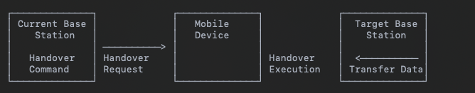
- Downlink (BS to Device) and Uplink (Device to BS) transmissions.- Handover. If the device moves out of range of the current base station, a handover is initiated to transfer the connection to a new base station without interrupting the service.
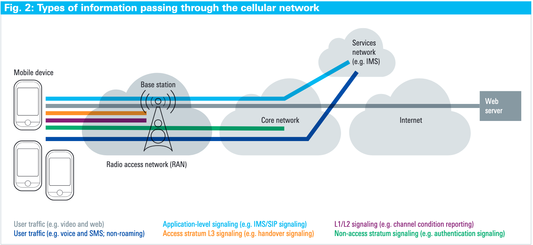
Signaling
As shown in the diagram above, there are a lot of references to something called "signaling". Signaling seems to be a shorthand for handling a lot of configuration and hand-off between tower and device and the core network. As far as I can tell they can be broken into 3 types.
- Access Stratum Signaling
- Set of protocols to manage the radio link between your phone and cellular network.
- Handles authentication and encryption
- Radio bearer establishment (setting up a dedicated channel for data transfer)
- Mobility management (handovers, etc)
- Quality of Service control.
- Non-Access Stratum (NAS) Signaling
- Set of protocols used to manage the interaction between your phone and the cellular network's core infrastructure.
- It handles tasks such as authentication, billing, and location services.
- Authentication with the Home Location Register (HLR)
- Roaming management
- Charging and billing
- IMSI Attach/ Detach procedure
- Lower Layer Signaling on the Air Interface
- This refers to the control signaling that occurs between your phone and the cellular network's base station at the physical or data link layer.
- It ensures reliable communication over the air interface, error detection and correction, and efficient use of resources (e.g., allocating radio bandwidth).
- Modulation and demodulation control
- Error detection and correction using CRCs (Cyclic Redundancy Checks)
High Level Overview of Signaling
- You turn on your phone (AS signaling starts).
- Your phone sends an Initial Direct Transfer (IDT) message to establish a radio connection with the base station (lower layer signaling takes over).
- The base station authenticates your phone using NAS signaling, contacting the HLR for authentication.
- Once authenticated, lower layer signaling continues to manage data transfer between your phone and the base station.
What is HLR?
Home Location Register contains the subscriber data for a network. Their IMSI, phone number, service information and is what negotiates where in the world the user physically is.
Duplexing
You have a lot of devices and you have a few towers. You need to do many uplinks and downlinks to many devices.
It is important that any cellular communications system you can send and receive in both directions at the same time. This enables conversations to be made, with either end being able to talk and listen as required. In order to be able to transmit in both directions, a device (UE) and base station must have a duplex scheme. There are a lot of them including Frequency Division Duplex (FDD), Time Division Duplex (TDD), Semi-static TDD and Dynamic TDD.
Duplexing Types:
- Frequency Division Duplex (FDD): Uses separate frequency bands for downlink and uplink signals.
- Downlink: The mobile device receives data from the base station on a specific frequency (F1).
- Uplink: The mobile device sends data to the base station on a different frequency (F2).
- Key Principle: Separate frequencies for uplink and downlink enable simultaneous transmission and reception.
┌──────────────┐              ┌──────────────┐
│  Base Station│              │   Mobile     │
│              │              │   Device     │
│  ──────────> │ F1 (Downlink)│ <──────────  │
│              │              │              │
│  <────────── │ F2 (Uplink)  │ ──────────>  │
└──────────────┘              └──────────────┘

Separate frequency bands (F1 and F2)- Time Division Duplex (TDD): Alternates between downlink and uplink signals over the same frequency band.
- Downlink: The base station sends data to the mobile device in a time slot.
- Uplink: The mobile device sends data to the base station in a different time slot using the same frequency.
- Key Principle: The same frequency is used for both uplink and downlink, but at different times.
 ┌──────────────┐                     ┌──────────────┐
 │  Base Station│                     │  Mobile Phone│
 │ (eNodeB/gNB) │                     │              │
 └──────────────┘                     └──────────────┘

     ───────────►  Time Slot 1 (Downlink)
                 (Base station sends data)

     ◄───────────  Time Slot 2 (Uplink)
                 (Mobile sends data)

     ───────────►  Time Slot 3 (Downlink)
                 (Base station sends data)

     ◄───────────  Time Slot 4 (Uplink)
                 (Mobile sends data)

    - The same frequency is used for both directions.
    - Communication alternates between downlink and uplink in predefined time slots.
Frame design
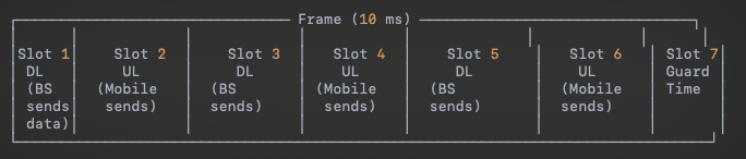
- Downlink/Uplink: There are predetermined time slots for uplink and downlink, but they can be changed periodically (e.g., minutes, hours).
- Key Principle: Time slots are allocated statically for longer durations but can be switched based on network traffic patterns (e.g., heavier downlink traffic during peak hours).
- A frame typically lasts 10 ms and is divided into time slots for downlink (DL) and uplink (UL).
- "Guard" time slots are used to allow switching between transmission and reception.
4. Dynamic Time Division Duplex (Dynamic TDD):
- Downlink/Uplink: Time slots for uplink and downlink are dynamically adjusted in real time based on instantaneous traffic demands.
- Key Principle: Uplink and downlink time slots are flexible and can vary dynamically to optimize the usage of the available spectrum in real-time, depending on the traffic load.
- See second diagram for what "guard periods" are. Basically windows to ensure there are gaps and the signal doesn't overlap.
 ┌──────────────┐                     ┌──────────────┐
 │  Base Station│                     │  Mobile Phone│
 │ (eNodeB/gNB) │                     │              │
 └──────────────┘                     └──────────────┘

     ───────────►  Time Slot 1 (Downlink)
     ───────────►  Time Slot 2 (Downlink)
     ───────────►  Time Slot 3 (Downlink)
     ◄───────────  Time Slot 4 (Uplink)
     ───────────►  Time Slot 5 (Downlink)

     ◄───────────  Time Slot 6 (Uplink)

    - More slots for downlink in scenarios with high download traffic (e.g., streaming video).
    - Dynamic slot assignment can change depending on the real-time demand.
┌──────────────┐ ┌──────────────┐
│ Base Station│ │ Mobile Phone│
│ (eNodeB/gNB) │ │ │
└──────────────┘ └──────────────┘
───────────► Time Slot 1 (Downlink)
───────────► Time Slot 2 (Downlink)
[Guard Period] (Switch from downlink to uplink)
◄─────────── Time Slot 3 (Uplink)
[Guard Period] (Switch from uplink to downlink)
───────────► Time Slot 4 (Downlink)
- Guard periods allow safe switching from one direction to another.
- Guard periods prevent signals from overlapping and causing interference.Core
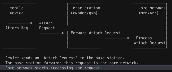
So I've written a lot about what the RAN does. But we haven't really touched on what the core network concept does. Basically once the device registers with the base station using the random access procedure discussed above, the device is enabled and allows the core network to do a bunch of stuff that we typically associate with "having a cellular plan".
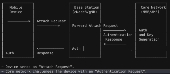
For modern devices when we say authentication we mean "mutual authentication", which means the device authenticates the network and the network authenticates the device. This is typically something like a subscriber-specific secret key and a random number to generate a response to the request sent by the device. Then the network sends an authentication token and the device compares this token with the expected token to authenticate the network. It looks like the following:
┌───────────────────────┐
│    Encryption &       │
│  Integrity Algorithms │
├───────────────────────┤
│  - AES (Encryption)   │
│  - SNOW 3G (Encryption│
│  - ZUC (Encryption)   │
│  - SHA-256 (Integrity)│
└───────────────────────┘

- AES: Strong encryption algorithm commonly used in LTE/5G.
- SNOW 3G: Stream cipher used for encryption in mobile communications.
- ZUC: Encryption algorithm used in 5G.
- SHA-256: Integrity algorithm ensuring data integrity.
The steps of the core network are as follows:
- Registration (also called attach procedure): The device connects to the core network (e.g., EPC in LTE or 5GC in 5G) to register and declare its presence. This involves the device identifying itself and the network confirming its identity.
- Mutual Authentication: The network and device authenticate each other to ensure a secure connection. The device verifies the network’s authenticity, and the network confirms the device’s identity.
- Security Activation: After successful authentication, the network and the device establish a secure channel using encryption and integrity protection to ensure data confidentiality and integrity.
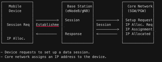
- Session Setup and IP Address Allocation: The device establishes a data session with the core network, which includes setting up bearers (logical paths for data) and assigning an IP address to enable internet connectivity.
How Data Gets To Phone
Alright we've talked about how the phone finds a tower to talk to, how the tower knows who the phone is and all the millions of steps involved in getting the mobile phone an actual honest-to-god IP address. How is data actually getting to the phone itself?
- Configuration for Downlink Measurement: Before downlink data transmission can occur, the mobile device (UE) must be configured to perform downlink measurements. This helps the network optimize transmission based on the channel conditions. Configuration messages are sent from the base station (eNodeB in LTE or gNB in 5G) to instruct the UE to measure certain DL reference signals.
- Reference Signal (Downlink Measurements): The mobile device receives reference signals from the network. These reference signals are used by the UE to estimate DL channel conditions. In LTE, Cell-specific Reference Signals (CRS) are used, and in 5G, Channel State Information-Reference Signals (CSI-RS) are used.
- DL Channel Conditions (CQI, PMI, RI): The mobile device processes the reference signals to assess the downlink channel conditions and generates reports such as CQI (Channel Quality Indicator), PMI (Precoding Matrix Indicator), and RI (Rank Indicator). These reports are sent back to the base station.
- DL Resource Allocation and Packet Transmission: Based on the UE’s channel reports (CQI, PMI, RI), the base station allocates appropriate downlink resources. It determines the modulation scheme, coding rate, MIMO layers, and frequency resources (PRBs) and sends a DL scheduling grant to the UE. The data packets are then transmitted over the downlink.
- Positive/Negative Acknowledgement (HARQ Feedback): After the UE receives the downlink data, it checks the integrity of the packets using CRC (Cyclic Redundancy Check). If the CRC passes, the UE sends a positive acknowledgement (ACK) back to the network. If the CRC fails, a negative acknowledgement (NACK) is sent, indicating that retransmission is needed.
- New Transmission or Retransmission (HARQ Process): If the network receives a NACK, it retransmits the packet using the HARQ process. The retransmission is often incremental (IR-HARQ), meaning the device combines the new transmission with previously received data to improve decoding.
Uplink is a little different but is basically the device asking for a timeslot to upload, getting a grant, sending the data up and then getting an ack that it is sent.
Gs
So as everyone knows cellular networks have gone through a series of revisions over the years around the world. I'm going to talk about them and just try to walk through how they are different and what they mean.
1G

- Starts in Japan, moves to Europe and then the US and UK.
- Speeds up to 2.4kbps and operated in the frequency band of 150 KHz.
- Didn't work between countries, had low capacity, unreliable handoff and no security. Basically any receiver can listen to a conversation.
2G
- Launched in 1991 in Finland
- Allows for text messages, picture messages and MMS.
- Speeds up to 14.4kbps between 900MHz and 1800MHz bands
- Actual security between sender and receiver with messages digitally encrypted.
Wait, are text messages encrypted?
So this was completely new to me but I guess my old Nokia brick had some encryption on it. Here's how that process worked:
- Mobile device stores a secret key in the SIM card and the network generates a random challenge and sends it to the mobile device.
- The A3 algorithm is used to compute a Signed Response (SRES) using the secret key and the random value.
- Then the A8 algorithm is used with secret and the random value to generate a session encryption key Kc (64-bit key). This key will be used for encrypting data, including SMS.
- After the authentication process and key generation, encryption of SMS messages begins. GSM uses a stream cipher to encrypt both voice and data traffic, including text messages. The encryption algorithm used for SMS is either A5/1 or A5/2, depending on the region and network configuration.
- A5/1: A stronger encryption algorithm used in Europe and other regions.
- A5/2: A weaker variant used in some regions, but deprecated due to its vulnerabilities.
- The A5 algorithm generates a keystream that is XORed with the plaintext message (SMS) to produce the ciphertext, ensuring the confidentiality of the message.
So basically text messages from the phone to the base station were encrypted and then exposed there. However I honestly didn't even know that was happening.
TSMA and CDMA
I remember a lot of conversations about GSM vs CDMA when you were talking about cellular networks but at the time all I really knew was "GSM is European and CDMA is US".
- TSMA is GSM and uses time slots
- CDMA allocates each user a special code to communicate over multiple physical channels
- GSM is where we see services like voice mail, SMS, call waiting
EDGE
So everyone who is old like me remembers EDGE on cellphones, including the original iPhone I waited in line for. EDGE was effectively a retrofit you could put on top of an existing GSM network, keeping the cost for adding it low. You got speeds on 9.6-200kbps.
3G
- Welcome to the year 2000
- Frequency spectrum of 3G transmissions is 1900-2025MHz and 2110-2200MHz.
- UTMS takes over for GSM and CDMA2000 takes over from CDMA.
- Maxes out around 8-10Mbps
- IMT-2000 = 3G
So let's just recap quickly how we got here.
- 2G (GSM): Initially focused on voice communication and slow data services (up to 9.6 kbps using Circuit Switched Data).
- 2.5G (GPRS): Introduced packet-switched data with rates of 40-50 kbps. It allowed more efficient use of radio resources for data services.
- 2.75G (EDGE): Enhanced the data rate by improving modulation techniques (8PSK). This increased data rates to around 384 kbps, making it more suitable for early mobile internet usage.
EDGE introduced 8-PSK (8-Phase Shift Keying) modulation, which allowed the encoding of 3 bits per symbol (as opposed to 1 bit per symbol with the original GSM’s GMSK (Gaussian Minimum Shift Keying) modulation). This increased spectral efficiency and data throughput.
EDGE had really high latency so it wasn't really usable for things like video streaming or online gaming.
- 3G (WCDMA): Max data rate: 2 Mbps (with improvements over EDGE in practice). Introduced spread-spectrum (CDMA) technology with QPSK modulation.
- 3.5G (HSDPA): Enhanced WCDMA by introducing adaptive modulation (AMC), HARQ, and NodeB-based scheduling. Max data rate: 14.4 Mbps (downlink).
So when we say 3G we actually mean a pretty wide range of technologies all underneath the same umbrella.
4G
- 4G or as it is sometimes called LTE evolved from WCDMA. Instead of developing new radio interfaces and new technology existing and newly developed wireless system like GPRS, EDGE, Bluetooth, WLAN and Hiper-LAN were integrated together
- 4G has a download speed of 67.65Mbps and upload speed of 29.37Mbps
- 4G operates at frequency bands of 2500-2570MHz for uplink and 2620-2690MHz for downlink with channel bandwidth of 1.25-20MHz
- 4G has a few key technologies, mainly OFDM, SDR and Multiple-Input Multiple-Output (MIMO).
- OFDM (Orthogonal Frequency Division Multiplexing)
- Allows for more efficient use of the available bandwidth by breaking down data into smaller pieces and sending them simultaneously
- Since each channel uses a different frequency, if one channel experiences interference or errors, the others remain unaffected.
- OFDM can adapt to changing network conditions by dynamically adjusting the power levels and frequencies used for each channel.
- SDR (Software Defined Radio)
- Like it sounds, it is a technology that enables flexible and efficient implementation of wireless communication systems by using software algorithms to control and process radio signals in real-time. In cellular 4G, SDR is used to improve performance, reduce costs, and enable advanced features like multi-band support and spectrum flexibility.
- MIMO (multiple-input multiple-output)
- A technology used in cellular 4G to improve the performance and capacity of wireless networks. It allows for the simultaneous transmission and reception of multiple data streams over the same frequency band, using multiple antennas at both the base station and mobile device.
- Works by having both the base station and the mobile device equipped with multiple antennas
- Each antenna transmits and receives a separate data stream, allowing for multiple streams to be transmitted over the same frequency band
- There is Spatial Multiplexing where multiple data streams are transmitted over the same frequency band using different antennas. Then Beamforming where advanced signal processing techniques to direct the transmitted beams towards specific users, improving signal quality and reducing interference. Finally Massive MIMO where you use a lot of antennas (64 or more) to improve capacity and performance.
- OFDM (Orthogonal Frequency Division Multiplexing)
5G
- The International Telecommunication Union (ITU) defines 5G as a wireless communication system that supports speeds of at least 20 Gbps (gigabits per second), with ultra-low latency of less than 1 ms (millisecond).
- 5G operates on a much broader range of frequency bands than 4G
- Low-band frequencies: These frequencies are typically below 3 GHz and are used for coverage in rural areas or indoor environments. Examples include the 600 MHz, 700 MHz, and 850 MHz bands.
- Mid-band frequencies: These frequencies range from approximately 3-10 GHz and are used for both coverage and capacity in urban areas. Examples include the 4.5 GHz, 6 GHz, and 24 GHz bands.
- High-band frequencies: These frequencies range from approximately 10-90 GHz and are used primarily for high-speed data transfer in dense urban environments. Examples include the 28 GHz, 39 GHz, and 73 GHz bands.
- 5g network designs are a step up in complexity from their 4g predecessors, with a control plane and a userplane with each plane using a separate network function. 4G networks have a single plane.
- 5G uses advanced modulation schemes such as 256-Quadrature Amplitude Modulation (QAM) to achieve higher data transfer rates than 4G, which typically uses 64-QAM or 16-QAM
- All the MIMO stuff discussed above.
What the hell is Quadrature Amplitude Modulation?
I know, it sounds like a Star Trek thing. It is a way to send digital information over a communication channel, like a wireless network or cable. It's a method of "modulating" the signal, which means changing its characteristics in a way that allows us to transmit data.
When we say 256-QAM, it refers to the specific type of modulation being used. Here's what it means:
- Quadrature: This refers to the fact that the signal is being modulated using two different dimensions (or "quadratures"). Think of it like a coordinate system with x and y axes.
- Amplitude Modulation (AM): This is the way we change the signal's characteristics. In this case, we're changing the amplitude (magnitude) of the signal to represent digital information.
- 256: This refers to the number of possible states or levels that the signal can take on. Think of it like a binary alphabet with 2^8 = 256 possible combinations.
Why does 5G want this?
- More information per symbol: With 256-QAM, each "symbol" (or signal change) can represent one of 256 different values. This means we can pack more data into the same amount of time.
- Faster transmission speeds: As a result, we can transmit data at higher speeds without compromising quality.
Kubernetes and 5G
Kubernetes is a popular technology in 5G and is used for a number of functions, including the following:
- Virtual Network Functions (VNFs): VNFs are software-based implementations of traditional network functions, such as firewalls or packet filters. Kubernetes is used to deploy and manage these VNFs.
- Cloud-Native Network Functions (CNFs): CNFs are cloud-native applications that provide network function capabilities, such as traffic management or security filtering. Kubernetes is used to deploy and manage these CNFs.
- Network Function Virtualization (NFV) Infrastructure: NFV infrastructure provides the underlying hardware and software resources for running VNFs and CNFs. Kubernetes is used to orchestrate and manage this infrastructure.
Conclusion
So one of the common sources of frustration for developers I've worked with when debugging cellular network problems is that often while there is plenty of bandwidth for what they are trying to do, the latency involved can be quite variable. If you look at all the complexity behind the scenes and then factor in that the network radio on the actual cellular device is constantly flipping between an Active and Idle state in an attempt to save battery life, this suddenly makes sense.
Because all of the complexity I'm talking about ultimately gets you back to the same TCP stack we've been using for years with all the overhead involved in that back and forth. We're still ending up with a SYN -> SYN-ACK. There are tools you can use to shorten this process somewhat (TCP Fast Open) and changing the initial congestion window but still you are mostly dealing with the same level of overhead you always dealt with.
Ultimately there isn't much you can do with this information, as developers have almost no control over the elements present here. However I think it's useful as cellular networks continue to become the dominant default Internet for the Earth's population that more folks understand the pieces happening in the background of this stack.